| Capacity |
: |
kVAR |
| Phase |
: |
Delta connection |
| Input voltage range |
: |
380/415/440volt , 3phase , 50/60Hz |
| System |
: |
Balanced/Unbalanced |
| Switching Type |
: |
S-type (SCR switching) |
| Construction |
: |
Indoor, floor mounting powder coated |
| Control. Range setting for PF |
: |
- 0.8 Inductive (lag to +0.8 capacitive (lead)– 0.8 Capacitive |
| Insulation |
: |
Class “B” |
| Humidity |
: |
Upto 95% Rh |
| Operating temperature |
: |
-0.5 to 45degree C |
| PROTECTION: |
|
|
| Input MCB/MCCB |
: |
For incoming APFC panel |
| Input MCB/MCCB |
: |
For PF CAP of each step/bank |
| Untuned line choke |
: |
For PF CAP of each step/bank of 4% line voltage |
| Thermal protection |
: |
Excess heating of heatsink at 70 degree C |
| Cooling fan |
: |
Current sensing for cubicle and each heatsink |
| INDICATIONS |
: |
Mains on ------ control on ----- APFC panel on
Cooling fan on ---- Step MCB on ---------Static switch on |
| INSTRUMENTATION |
: |
APFC panel input voltmeter with selector switch
AC Current meter with selector switch and CT
Power manager (optional) |
| SWITCHING TYPE |
: |
Static switch / firing modules for each step |
| APFC CONTROLLER |
|
|
| Indications |
|
Auto |
|
Three digit numeric display |
|
Manual |
|
Capacitive And Inductive .(leading and lagging) |
|
Current |
|
Step ON Indicator |
|
THD(total harmonic distortion) |
|
Up Button |
|
Set Cos ø |
|
Mode / Scroll Button |
|
C/K |
|
Down Button |
|
Sensitivity |
|
Program Button |
|
Recon Time |
|
Rated Steps |
|
Switch Program |
|
|
|
THD (total harmonic distortion) Limit |
|
|
| |
|
|
|
Alarm assign for one of given parameters – current THD, current <3% rated value , current >110% rated value , voltage <85% rated value , voltage>110% rated value`, low PF when all cap. connected, Hi PF when no cap. connected, auto c/k step measurement error (manual setting required) , auto CT polarity error. |
| |
|
|
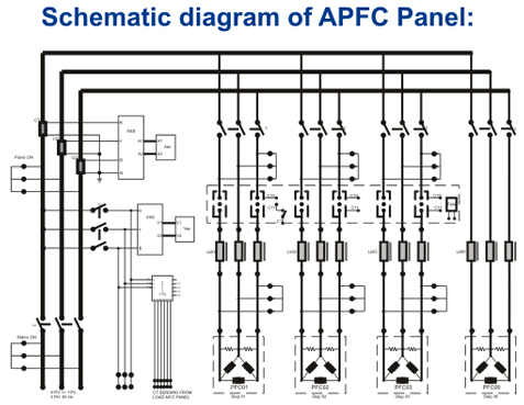
TECHNICAL DATA |
1) AUXILLARY SUPPLY |
: |
Supply voltage: 220VAC /415VAC -15% / +10% 50/60Hz consumption – 10VA max. |
2) CURRENT INPUT |
: |
Rated current In : 5A operating limits : 0.15A -6.5A 50/60Hz |
3) RELAY OUTPUT |
: |
Number of output : 6/8/12/14 (PFR60/PFR80/PFR120/PFR140)
|
| |
Rated capacity-5A 250VAC Contacts: NO TYPE Max current for common terminals: 12A continuous |
| 4) CONTROL RANGE: |
: |
C/K setting : 0.03 – 1.20 / atc switching sensitivity : 5-600 s/steps
|
| |
|
Reconnection time for same step : 5-240s THD threshold : 0.20-3.0(20%-300%)/off |
| |
|
Switching program : automatic/automatic rotate/manual/four quadrant |
| |
|
Rated step coefficient :0/1/2/3/4/5/6/8/12/16 |
5) MECHANICAL |
: |
Mounting: panel mounting dimension (H x W x D) 144 x 144 x 91 wt.: 1kg |
| |
|
|
|
| |
|
|
K Type Specification |
| APFC PANEL |
: |
K TYPE |
| Capacity |
: |
kVAR |
| Phase |
: |
Delta connection |
| Input voltage range |
: |
380/415/440volt, 3phase, 50/60Hz |
| System |
: |
Balanced/unbalanced |
| Switching Type |
: |
K-type (contactor switching) |
| Construction |
: |
Indoor, floor mounting powder coated |
| Control Range setting for PF |
: |
0.8 Inductive – 0.8 Capacitive |
| Insulation |
: |
Class “B” |
| Humidity |
: |
Upto 95% Rh |
| Operating temperature |
: |
-0.5 to 45degree C |
PROTECTION : |
| Input MCB/MCCB |
: |
For incoming APFC panel |
| INDICATIONS |
: |
Mains on ------ control on ----- APFC panel on
Cooling fan on --- Step MCB on |
| INSTRUMENTATION |
: |
APFC panel input voltmeter with selector switch
AC Ammeter with selector switch and CT
Power manager (optional) |
| SWITCHING TYPE |
: |
Contactor |
APFC CONTROLLER |
|
Indications |
|
3 digit numeric display |
|
Manual |
|
Capacitive and Inductive. (Leading and lagging) |
|
Current |
|
Step ON Indicator |
|
Thd (total harmonic distortion) |
|
Up Button |
|
Set Cos ø Power Factor |
|
Mode / Scroll Button |
|
C/K |
|
Down Button |
|
Sensitivity |
|
Program Button |
|
Recon Time |
|
Rated Steps |
| Switch Program |
|
|
Thd (total harmonic distortion) Limit
Alarm assign for one of given parameters – current thd, current <3% rated value, current >110% rated value, voltage <85% rated value, voltage>110% rated value`, low pf when all cap. connected, hi pf when no cap. connected, auto c/k step measurement error (manual setting required), auto CT polarity error. |
| |
|
|
TECHNICAL DATA |
1) AUXILLARY SUPPLY |
: |
Supply voltage: 220VAC/415VAC -15% / +10% , 50/60 Hz consumption – 10VA max |
2) CURRENT INPUT |
: |
Rated current In: 5A operating limits: 0.15A -6.5A 50/60Hz |
3) RELAY OUTPUT |
: |
Number of output: 6/8/12/14 (PFR60/PFR80/PFR120/PFR140)
|
| |
Rated capacity-5A 250VAC Contacts: NO TYPE Max current for comman terminals: 12A continuous |
4) CONTROL RANGE: |
: |
C/K setting : 0.03 – 1.20 / atc switching sensitivity : 5-600 s/steps
|
| |
|
Reconnection time for same step : 5-240s thd threshold : 0.20-3.0(20%-300%)/off |
| |
|
Switching program : automatic/automatic rotate/manual/four quadrant |
| |
|
Rated step coefficient : 0/1/2/3/4/5/6/8/12/16 |
5) MECHANICAL |
: |
Mounting: panel mounting dimension (H x W x D) 144 x 144 x 91 wt.: 1kg |